CN
CN May 07, 2026
The first time you watch a roll of printed BOPP film disappear into a compact machine and come out the other side as a crystal‑clear, wrinkle‑free laminate, the process almost feels like a magic trick. But behind that smooth motion lies a carefully choreographed sequence of tension control, heating, and precision web handling. Understanding how that choreography functions does more than satisfy curiosity — it helps operators slash setup waste, cut downtime, and produce consistent results shift after shift.
Whether you are running short‑run digital labels or high‑volume flexible packaging, knowing what happens inside the lamination tunnel is the foundation of every optimisation conversation that follows.
The problem with treating a laminator like a black box
Many production floors treat the laminator as a sealed unit: feed material in, set a temperature, and hope the result passes QC. Over time, this leads to three recurring headaches:
-
Excessive film waste during job changeovers often reaching 6–8% of the total roll length.
-
Silver streaks and bubbles that only appear after slitting, when the reels are already on the way to the customer.
-
Unplanned stops caused by web breaks, which can erase an entire shift’s efficiency gains in minutes.
According to the Flexible Packaging Association’s 2024 operational benchmark, unscheduled downtime in laminating and coating lines averages 11.5 hours per month, and roughly a third of those incidents trace back to incorrect tension or temperature profiling — both of which stem from a weak understanding of how the machine actually works.
The good news is that the underlying principles are straightforward once you break them down. And when every operator on the floor understands them, the machine stops being a black box and starts being a dial you can turn to hit next‑level productivity.
How vertical web path changed lamination productivity
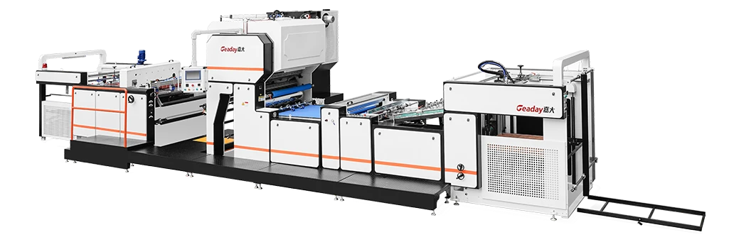
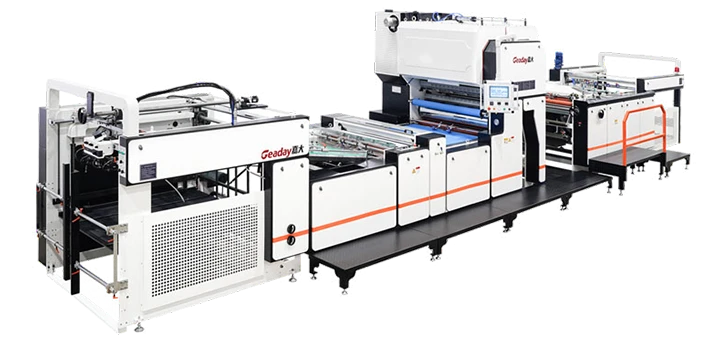
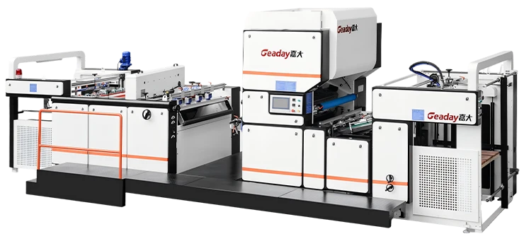
Before diving into the steps, it is worth noting why the vertical layout became the default for modern high‑speed systems like the ones Geaday has designed. In a traditional horizontal laminator, the web travels a long, flat path that occupies significant floor space and introduces multiple direction changes. A vertical machine stacks the unwind, coating, laminating, and rewind sections in a tower format.
This geometry offers three tangible benefits:
-
Smaller footprint — a vertical laminator often occupies 30–40% less floor space than a horizontal line with equivalent web width and speed.
-
Better web stability — the vertical path uses gravity to help keep the web centered, reducing the need for aggressive edge guides.
-
Faster heat transfer — shorter distances between heating and nip sections mean the film reaches target temperature more quickly, allowing higher line speeds.
For converters running 250–400 m/min, these factors translate directly into more saleable square meters per shift.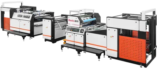
Step‑by‑step: what happens from unwind to rewind
Understanding the process inside an automatic vertical laminator means following the web through six key zones.
1. Unwind and splicing
The process starts at the top of the machine, where the printed substrate and the laminating film each sit on their own unwind stations. Most high‑output vertical laminators are equipped with automatic flying splice units. When the running roll nears its core, a fresh roll is accelerated to line speed and the tail of the old web is bonded to the leading edge of the new one — all without stopping the line.
2. Tension control and web guiding
As the substrate descends, it passes through a series of dancer rollers and load cells that continuously measure tension. Typical setpoints for PET substrates 12–23 µm thick range between 80–150 N/m, depending on width and speed. An ultrasonic or optical web guide adjusts lateral position to within ±0.2 mm, preventing telescoping at the rewind.
3. Corona treatment (when needed)
If the substrate has low surface energy — common with BOPP and PE — a corona discharge unit increases its dyne level to improve adhesive anchorage. This is a momentary, controlled plasma treatment that typically raises surface energy from below 38 dynes to 48–52 dynes, creating the microscopic roughness needed for a mechanical bond.
4. Adhesive application and drying
Solvent‑free, water‑based, or solvent‑based adhesive is applied to one web via a multi‑roller coating head. In a vertical laminator, the adhesive station is positioned mid‑tower. After application, the coated web passes through a drying tunnel where hot air evaporates the carrier. The tunnel length and temperature zones are designed to achieve over 95% solvent removal before the lamination nip, preventing solvent entrapment that would cause bubbles later.
5. Lamination nip — where the magic happens
This is the heart of the machine. The two webs meet at a heated chrome‑plated roller and a rubber pressure roller. Temperatures typically sit between 60–90 °C, with a line pressure of 4–6 N/mm². Achieving a flawless bond here depends on three things happening simultaneously: the adhesive must be activated by heat, the pressure must be uniform across the full width, and both webs must enter the nip at exactly the same tension. Any imbalance creates curl or delamination.
6. Cooling and rewind
Once bonded, the laminated web passes through a chilled roller section that quickly reduces the temperature below the adhesive’s softening point. From there, the web enters the rewind station, which on modern systems often includes taper tension control — gradually reducing winding tension as the roll diameter grows — to prevent blocking and starring defects.
Throughout this entire sequence, the machine’s PLC monitors several hundred data points per second. A well‑tuned system can switch from one job recipe to the next in under three minutes. If you want to see how these functions come together in a production‑grade architecture, you can review the modular configuration options that Geaday ships with as standard.
Three common setup mistakes and how to avoid them
Even a precisely engineered vertical laminator will produce scrap if the setup parameters are not aligned with the materials in use. Three errors show up repeatedly across converting operations:
| Mistake | Symptom | Root Cause | Quick Fix |
|---|---|---|---|
| Mismatched unwind tension | Curling towards the tighter web | Tension ratio not adjusted for thickness modulus | Calculate required tension using E × t × width formula and set dancer feedback accordingly |
| Nip temperature too high | Orange peel effect, edge shrinkage | Film residence time not recalibrated for new gauge | Run a bead‑to‑bead profile test and reduce temperature in 5 °C increments |
| Excessive winding hardness | Starring or telescoping at customer site | No taper tension or taper set too low | Enable taper mode; aim for 5–10% hardness fall‑off from core to outer layer |
Each of those fixes costs next to nothing compared to the expense of a rejected truckload. An operator who can diagnose the symptom and link it back to the specific zone in the machine becomes the most valuable person on the shift.
According to a process engineering manager at a large North American flexible packaging group — who recently line‑trialed a high‑speed vertical laminator with integrated recipe management — the biggest change wasn’t the hardware speed boost but the fact that “the line now automatically adapts tension to substrate thickness, so junior operators get the same results as our 20‑year veterans.” That kind of expertise, baked into the controls architecture, is what shifts lamination from an art to a repeatable science.
What separates a good laminator from a great one
When you are comparing systems, a few design choices make an outsized difference over the machine’s 15‑ to 20‑year lifespan:
-
Quick‑change coating head — systems that use a cart‑based or pivoting head let you switch between solvent‑free and water‑based adhesive in under 10 minutes.
-
Independent servo drives — each axis (unwind, coating, nip, rewind) driven by its own motor rather than a single line shaft eliminates gear backlash and gives far finer tension resolution.
-
Recipe management with real‑time viscosity control — automatically adjusting adhesive metering based on temperature and humidity keeps coat weight within a ±0.2 g/m² window.
-
Remote diagnostics — the ability for OEM engineers to securely access the PLC for troubleshooting reduces mean time to repair by as much as 40% in reported field data.
These are not abstract specs. They determine whether your line produces 2 million or 2.3 million square meters of sellable laminate per month. When you are ready to compare how different machines stack up on these four practical measures, the detailed architecture breakdown illustrates what a purpose‑built vertical platform can deliver.
Bringing it back to your production reality
The step‑by‑step mechanics inside a vertical laminator are built on well‑established web handling physics. What has changed in the last five years is how deeply automation is now embedded at every stage — from flying splice to taper tension — and how that automation fundamentally reduces the experience threshold for producing high‑quality laminate.
If you are running a horizontal line that is over 12 years old and you are seeing waste figures north of 5%, the bottleneck likely is not your people; it is the machine’s ability to self‑correct in real time. Moving to a vertical configuration with integrated tension control and quick‑change modules often delivers a payback period of 14 to 20 months based solely on film and adhesive savings.
Of course, the right solution for your product mix depends on your substrates, typical run lengths, and growth plans. For a personalised walk‑through of what throughput improvement looks like on your specific SKU mix, reach out for a technical scoping — the engineering team can model the numbers with your data, not generic averages.
The operating principles described in this article are based on publicly available technical literature and composite field experience. Individual machine performance varies with substrate, adhesive chemistry, and ambient conditions. Always consult the original equipment manufacturer’s guidelines when adjusting process parameters.